

Synthesis to sign-off: Tackling real-time issues in STA, SDC, PNR & more
Ganesh Lokunde, Lead Engineer, PD/STA, Eteros Technologies
4180 ViewsTable of Contents
1. Register to Clock Gating Timing violations and fixing!
Background
ICGs are used in the place of normal Clock Gaters as they can help avoid glitches in the Clock reaching the Flops. ICGs are helpful in the design to reduce Dynamic Power consumption by gating the Clock reaching the Clock pin of the flops when the data reaching the flop is not switching.
Problem Statement
We have a Reg2ClkGate setup violations and there are no cells in the enable path reaching the EN pin of CG. We must fix the setup violation either by pushing the clock reaching the CP pin of CG or pull the clock at launch flipflop.
For the problem in hand let’s focus on the impact of clock pushing.
Output of the ICG reaches a lot of flops to which it is gating the clock. Thus, pushing the CP pin of CG indirectly pushes all the flops which are in the fanout of the ICG. Thus, we can’t blindly push the clocks unless we are sure about the impact it has on all the flops in the fanout.
As shown in figure 1, we have added “Pre-Fanout Flops” & “Post-Fanout Flops”. Timing paths launching from Pre-Fanout Flops and also timing paths captured at Post-Fanout Flops are also affected due to clock push at the CG.
Data launched from “Pre-Fanout Flops” is getting captured at the “Fanout Flops”. Data launched from “Fanout Flops” are being captured at the “Post-Fanout Flops”.
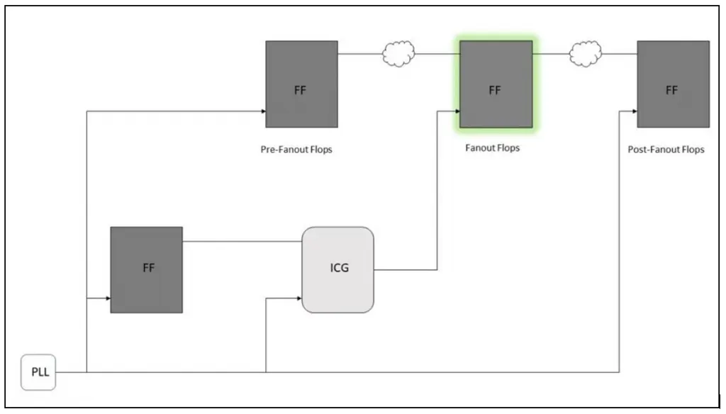
Figure 1: Register to Clock Gating
Proposed Solution
Clock Pushing at CG indirectly pushes the Clock reaching all the “Fanout Flops”. Thus, two new sets of timing paths must be considered and checked.
First Set – Paths with data launching from “Pre-Fanout Flops” and capturing at “Fanout Flops”
Second Set – Paths data launching from “Fanout Flops” and Capturing at “Post-Fanout Flops”
If Clock is pushed at Clock Gater’s clock pin to resolve setup violations, below 3 setup of timing paths must be checked.
1. Hold timing to the “First Set” as mentioned above. As we are indirectly pushing the Clock reaching “Fanout Flops” this aids in Setup time of “First Set” but worsens Hold time.
report_timing -to <Fanout Flops/D> -early
2. Setup Timing to the “Second Set”. As Pushing CG CP pin indirectly pushes the “Fanout Flops” this aids in Hold timing of Second Set but worsens Setup.
report_timing -through <Fanout Flops/CP> -late
3. 3. Hold Time of “Register” to “CG” checks.
2. RTL Inserted Clock Gating Cells & related Timing Constraints
Background
Clock Gater can be identified from a timing library (.lib) file through below attribute in .lib clock_gating_intergrated_cell : {string/generic};
When the attribute value is set to string, it should be a concatenation of up to 4 string values that describe the cell’s functionality
First String defines the type of sequential cell. E.g., latch, flip-flop, or none.
Second String defines whether the logic is appropriate for negative or positive edge triggered registers. Possible values are “posedge” or “negedge”
Third String (optional) specifies whether the test control is present before or after the latch or flip-flop or it doesn’t exist.
Fourth String specifies whether it has observability logic or not. Possible values are “obs” or “none”.
The rough structure of an ICG in .lib looks like below.
Cell (ICG) {
Clock_gating_intergrated_cell: latch_posedge_precontrol;       => Latch suitable for positive edge triggered & has test control logic before latch.

.
    Pin (TE) {
        clock_gating_test_pin : true;
        ..
    }
    Pin (CP) {
        Clock_gate_clock_pin : true;
        ..
    }
    Pin (EN) {
        Clock_gate_enable_pin : true;
    }
}
Problem Statement
Elaboration issues observed on the RTL inserted ICG cells because TE pins of ICG are left unconnected at the elaboration stage.
Impact of using Disabling Clock Gating checks in SDC before Mapping?
Proposed Solution for 1
Clock Gaters which have TE (test enable pin) are usually logically connected while scan stitching in Synthesis flow. This is controlled by the commands below in Genus tool.
lp_clock_gating_test_signal – Sets which signal Test Enable of CG should connect to. clock_gating connect_test – Tool starts connecting TE pin of CG to signal defined through above command.
If there are RTL inserted ICG cells present in the design, then TE pins of these cells will be left floating until scan stitching is done. Scan stitching doesn’t happen until the later stages of Synthesis. Thus, we need to connect TE pins to either a signal which controls ICG TE pins or tie it to constant before Elaboration to avoid any elab issues.
Proposed Solution for 2
Disabling Clock Gating Checks can be specified in SDC using the command below.
set_disable_clock_gating_checks.
However, SDC is read just after elaboration in Synthesis. Thus, all the cells in the design are not mapped yet. Thus, Tool throws a warning stating CG checks can’t be disabled in unmapped instances. We may see unwanted CG timing violations displayed after Synthesis and even after Routing in PNR in case these CG checks are not disabled properly.
Remove the “set_disable_clock_gating_checks” from SDC and source it just after Mapping is done.
3. Logically Exclusive Clock Groupings
The Set Clock Groups (set_clock_groups) constraint allows you to specify which clocks in the design are unrelated. By default, the Timing Analyzer assumes that all clocks are related, and that all transfers between those clock domains are valid for timing analysis.
You define the clocks to be included in the groups and define the relationship between each group using one of the 3 below categories.
- Physically Exclusive
- Asynchronous
- Logically Exclusive
Physically Exclusive are defined for clocks that are not active in the same mode. Func clocks and scan clocks won’t exist physically at the same time in the Design.
Asynchronous are defined on clocks which are a part of different PLL and there is no phase relationship between each other and thus SI impact won’t be there between each other.
Timing paths will also not be valid, and the STA engine doesn’t check for timing for clocks defined as asynchronous.
Logically Exclusive are defined on clocks which exist in the same mode but not at the same time. For example, consider 2 clocks as input to the Clock multiplexer and only one clock exists logically downstream at the output of the Clock Mux. We won’t be seeing any valid paths from clk1 and clk2 in the above scenario, but SI effect is considered.
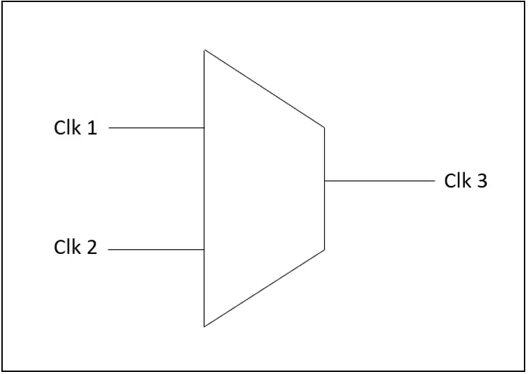
Figure 2: Logically Exclusive clocks
Create_generated_clock clock3
-master [get_clocks clk1]
-source <clock generation point of master clock – clk1>
-divide_by 1
<output pin of Mux (Clock generation point of clock3)>
Set_clock_groups -logically_exclusive -group clk1 -group clk2
4. Combinational Loops and their impact on timing
Background
Combinational Loop is formed by signal starting from input of combinational gate, after passing through one or more combinational logic, comes back to the same combo gate from which it started without entering any sequential element like flip-flop etc.
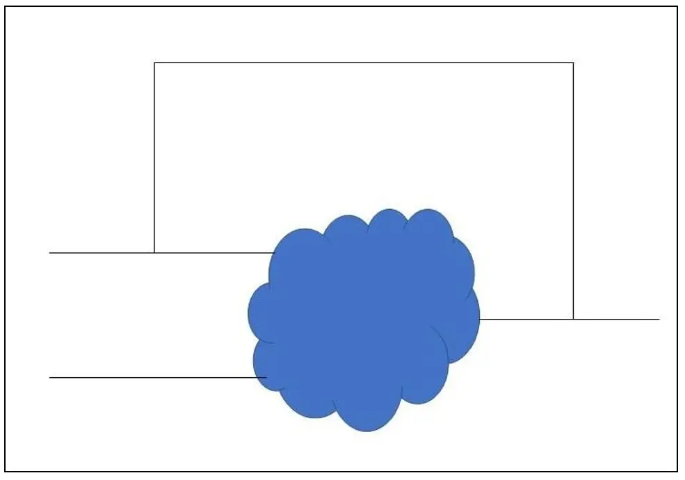
Figure 3: Combinational Loop
1. Combinational loops occur when left hand side of arithmetic expression also appears on right hand side in HTL code.
Eg:
Z =< Z nand B
assign out = out + incr;
2. Unintended Latch Inference. Latch is inferred unintentionally based on how the HDL code is written. For example, using if else statement in HDL code infers a Mux. But if we missed else statement in the code. Code by default infers a latch there and takes the other input of Mux same as output.
If (sel == 1’b0)
Y = I0; #Else statement is missed.
Tool infers a latch as shown below for the above code.
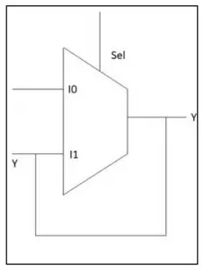
Figure 4: Latch Inference
Y = I0;
Else
Y = Y;
Why should combinational loops be avoided?
Combinational loop behavior generally depends on the propagation delays through the logic involved in the loop. Propagation delays can change based on various factors including input transition and output load etc. which means the behavior of the loops is unpredictable.
Most tools break the combinational loops to process the design. Different tools may open the loop differently and process it in a way different from the original design content. In such a situation where tools break the loops, certain paths will never be timed.
Solution
We can check with the Design team and break the timing arcs ourselves in SDC using set_disable_timing. So that we have control over the paths that will be timed and not some random path selected by the tool.
Eg: set_disable_timing [get_cells <Hard Macro>] -from A -to B
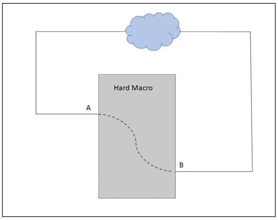
Figure 5: Combinational loop through Hard Macro
5. PBA in shift corners
Background
Difference between GBA & PBA?
Consider a combinational gate with 2 inputs A & B. By default, while timing analysis the tool picks up the worst slew of both the inputs while computing the cell delay for Setup Analysis. Similarly, the tool picks up the best slew of both the inputs while computing the cell delay for Hold Analysis. Tool picks up the worst and best slews irrespective of which input is in the current analyzed timing path. This gives us unnecessary pessimism. This is called Graph Based Analysis.
Path Based Analysis: The tool considers the actual slews for the arcs encountered while traversing any timing path instead of blindly taking the worst slew for Setup & best slew for Hold. Thus, PBA methods removed unnecessary optimism while doing timing analysis.
Why not use PBA instead of GBA?
Though PBA is more accurate and gives us the correct violations, it has a heavy toll on the run-time as well as resources (memory) as it must take the actual slew values for each and every timing path traversed.
Problem Statement
Though as described above PBA is more accurate than GBA and we observe difference in slack numbers compared to GBA & PBA. PBA mostly has less slack numbers and is used as a signoff criteria for closing timing. When we run PBA for Shift corners, we won’t see much difference in slack numbers from GBA to PBA. They are almost equal. What’s the actual reason?
Solution
Shift modes the data is shifted from one Scan flop to another from Output of Flip-flop through the data to SI input of Capture flip-flop. The data path in shift modes consists only of buffers or inverters in Shift mode. The data path doesn’t contain any logic as it only needs to shift the values from one flop to other along the scan chain.
Since data path doesn’t contain any complex logic cells with 2 or more inputs and it only has single input cells like buffers or inverters, though we enable PBA, we won’t see much improvement in the slack numbers compared to GBA.
Despite the above reasons it is best practice to Sign-off Timing using PBA.
6. Defining Skew Groups before CTS with the help of SDC?
Background
While starting CTS we need to define the skew groups. CTS tool balances the clock with almost same Latency for the clocks defined in same skew groups.
Let’s have a scenario where a master clock is generating 3 different generated clocks. By default, while defining the clock groups, all the 4 clocks mentioned above (master clock and 3 generated clocks) will be defined in same clock groups indicating that there will be valid timing paths between all of them.
When there are valid timing paths between 2 clocks, we must ensure that all the sinks receive the clocks at almost equal time or else the Clock Skew will be very high and will observe lot of Setup & Hold violations.
Problem Statement
How do we accurately define Skew groups before starting CTS?
Solution
We can verify the clocks in the design through the SDC (set_clock_groups). Get a list of clocks belonging to the same PLL and find out which are synchronous to each other.
If the clocks are made asynchronous to each other and there are no valid timing paths between each other, we don’t need to balance the skew between them.
7. Miscellaneous
Problem Statement
Should traverse all the flops present in the timing library and get the flop with less library hold time.
Hold time of a flop will be dependent on two factors (data transition & clock transition). The Timing library doesn’t have a single value for hold time for a Flop. It has a table of values dependent on data transition and clock transition as explained above.
We cannot take the existing design and check for all the instantiated flops and query for hold time attribute. As we may have missed so many flops which are not instantiated in the design due to dont_touch or preserve attributes. We can write a script to instantiate all the flops from library into the design and provide connections to Data and Clock pins of the flops through a dummy port.
Start providing various values of data transition and clock transitions to the dummy ports and query the hold times for all the instantiated flops and take the best flop with less hold time.
Solution
All the flops in .libs won’t be used in the design. We need to instantiate cells with all the available libs of flops in the design.
Should provide dummy connection from port1 (data) to D input of added flops. Should provide dummy connection from port2 (Clock) to Clock input of added flops.
Create test clock on port2, Provide IO delay on port1 w.r.to test clock of port1, Set input transition on both the ports and clock transition on the test clock!
Thus, timing paths are constrained and report_timing can be used to query for hold time of all instantiated flops.
Note: Hold time of reg is function of data transition and clock transition, thus true value can only be found out when we provide inputs with varied transitions to D and CP pin of flop.
Script: (In Tempus)
set transition 0.025 ;# Vary the value accordingly for each iteration of the run.

alias gob get_object_name

alias soc sizeof_collection

##only once

set ports_used "Data Clock"

foreach port $ports_used {

    14

    set inst [gob [all_fanout -from $port -only_cells -levels 1]]

    set term I

    set net $port

    detachTerm $inst $term $net

}

set_interactive_constraint_modes func

create_clock -name "test_clock" -period 1 [get_ports Clock]

set_input_delay 0.3 -add_delay -clock test_clock -max [get_ports Clock]

set_input_delay 0.05 -add_delay -clock test_clock -min [get_ports Clock]

set_input_transition $transition [get_ports Clock]

set_input_transition $transition [get_ports Data]

set_clock_transition 0.025 [get_clocks test_clock]

set lib_cells_flops ""

set sequential [get_lib_cells * -filter "is_sequential"]

set latches [get_lib_cells * -filter "is_negative_level_sensitive||is_positive_level_sensitive"]

set ICG [get_lib_cells * -filter "is_integrated_clock_gating_cell"]

append_to_collection latches_ICG $ICG append_to_collection latches_ICG $latches

set flops [remove_from_collection $sequential $latches_ICG]

foreach_in_collection cell $flops {

    regsub -lineanchor {^.*\/} [gob $cell] {} var append lib_cells_flops "$var "

}

set cnt 0

set lib_cells_flops [lsort -u $lib_cells_flops]

foreach lib_cell $lib_cells_flops { set cnt [expr $cnt+1]

    add_inst ${lib_cell}_inst_${cnt} $lib_cell

    attachTerm ${lib_cell}_inst_${cnt} D Data -port Data

  regsub -lineanchor {^.*\/} [gob [get_pins -of_objects [get_cells ${lib_cell}_inst_${cnt} ] -filter "is_clock"]] {} CP

    attachTerm ${lib_cell}_inst_${cnt} $CP Clock -port Clock

}
This approach gives us a good understanding of the library hold times of a flop based on the transition at the Data and Clock inputs. We can use this at later stages of Timing Fixes to fix hold times by replacing existing flops with the best possible alternative with less hold time when there is no scope for any other fixes.
It also gives us a good understanding of all the flops provided in the timing library. Though flops are set as dont_use. When hold time is a major concern it gives us an alternative solution which can be used if needed.
Note: dont_use is set on the cells for a reason, and it’s not advised to use them blindly.
*********
Glossary
| STA | Static Timing Analysis |
|---|---|
| SDC | Synopsys Design Constraints |
| PNR | Place and Route |
| PBA | Path Based Analysis |
| CTS | Clock Tree Synthesis |
| ICG | Integrated Clock Gating |
| FF | Flip Flop |
| EN | Enable Pin |
| CG | Clock Gater |
| CP | Clock Pin |
| TE | Test Enable |
| RTL | Register Transfer Level |
| SI | Signal Integrity |
| HDL | Hardware Description Language |
| GBA | Graph Based Analysis |
| PLL | Phase Locked Loop |